Tuesday, August 1, 2017

Musings on my own bad memory


Memory is a fickle thing.

For instance, I believed the helmet on this system had over a dozen LEDs. Obviously I had confused it with another project. I imagined there was a speaker in the gun itself for the shooting sound. Maybe this was the case in some suits, but from what I've seen the speaker is in the helmet where it can be more clearly heard over the arena music track. My mistake, the gun sound board is in fact wired to the gun connector, as documented in this very blog. The sound board is not in the gun itself, however.

After seeing some of the old equipment, I seem to recall there being those peanut lights on either side of the face, but why are they there? My working theory is that they were originally meant to add a faint edge-lit glow to the face shield, but the shield wasn't used in the game so they may have fallen by the wayside. A second example of the equipment has LEDs there and so my refurbished helmet also does.

I had once imagined all discrete decade counters and 7-segment display encoders running the score display. Thank goodness the 74C925 was available when this unit was designed; it runs all 3 digits with its multiplexed output, a perfect choice for this application. There are decade counters but that's for counting scored points (and, by extension, for timing the delay before you can be hit again).

Monday, July 31, 2017

Home stretch

Reconstruction of the display pack is almost done. There seems to be a flaky connection somewhere causing the score to go up; this was a VERY common symptom back in the day. If I can find it I'm going to fix it. The helmet needs to be lined, and another polish would be good too. There's some crud to be scrubbed off the boxes and dirt on the plastic shell, and more work to be done on the fabric trim.

(Edit: I did find the bad connection on the terminal strip in the upper left corner of the battery box.)

Thursday, June 15, 2017

Reconstructing the helmet


The helmet being reconstructed has been gutted and its insides blown clean.


The helmet is upside-down on a cluttered workbench. The Styrofoam crush layer inside has wires running from place to place, powering the LEDs. The bench has a coil of more wire, a multimeter, a glue gun, pen and paper with a terminal diagram, and a screw terminal block.
Helmet cleaned up and being rewired.


The team color LEDs were not so good. One LED was too dim and did not match the others, and another one had a cracked leg. Both of these and their dropping resistors were replaced, and the whole chain rewired neatly.


There was no speaker; a 1980s vintage paper cone speaker was added. It fits perfectly in the recess provided.


A closer view of the interior of the helmet shows the terminal block installed in a wide notch that has been cut out of the Styrofoam. A speaker also sits in a hole in the foam. The LED wires have been taped and glued down.
Laying out the new wiring.
The terminal strip is new and serves to make repair easier, should it ever be needed.


The original harness was also secured with duct tape, but it was just trash. Sloppy connections, wads of wire, and a big pillar of ground wires soldered together in free space.

All of this was removed, including the peculiar stubby cable that was too short (and doesn't actually plug into any known connector). This new cable uses the correct mil-spec connector, plugs directly into the suit, and matches the original in appearance if not durability.

A close-up of a worn Amp CPC plastic connector next to an olive green military grade connector.
Incorrect helmet connector on left. Correct connector on right (plugs into back box on vest).

On the other end of this cable, I went with a cheap screw-terminal strip since this will be for display purposes only. All this and some layers of felt for appearance's sake complete the display helmet.


Wednesday, May 24, 2017

Considering the helmet


Time to catch up on posts. First, some reflection on the helmet I'm refurbishing.

The holes in the helmet being reconstructed do not match the one that was on display at the Laser Tag Museum, nor do they line up with my recollection. On the helmet for refurbishment there are two cheek holes; the next LEDs (one on each side) are only a few inches back; and there are no holes on the sides, front, or back for hit detectors.

The side view of a helmet with several holes for LEDs, which lay on the bench behind the helmet.
Side has two LEDs and a light bulb, but—alas, poor Yorick!no hit sensors.


Compare this to the helmet previously on display at the Museum in 2015, where each cheek has only one LED; the next LEDs have been moved up where they will be better visible from above; and sensors have been added which can be hit from the sides or from above. Since shoulder-top sensors and lights had not been invented in those days, these would be a must for multi-level arenas.
The side view of a helmet with two LEDs and a light sensor labeled.
Much easier to see or hit this player.


Returning to the reconstruction helmet, there is also a parietal cluster of four holes on the left side which could have had sensors; but if so, why only on one side, and all in one place?  There is nothing like this on the other sample.

A view of the crown of a helmet with four holes seen in a rough cluster.
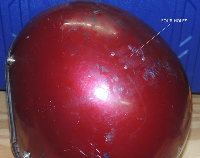
Suspiciously located over a rounded pocket that just happens to fit a small speaker.

The speaker was missing when the helmet arrived for reconstruction, but this is the most likely place for it, and perhaps it was meant to be heard from outside the helmet as a result of these holes.

A close-up view of a paper cone speaker.
The interior is now fitted with a vintage speaker.

I've tentatively concluded that this helmet was never fitted with hit sensors at all, which may explain why its cable and connector had only 4 wires (2 for LEDs, 2 for speaker) on a stubby cable with an Amp CPC connector which is not used anywhere else in the system.

I built the correct cable in the original style, long enough to reach the connector on the pack, which uses an Amp 3470 series Mil-spec connector ... unquestionably the single best design decision made on this pack design.

Two connectors (see next post).
Oddball connector on the left. Correct, military grade connector on the right (granted, with strain relief suitable for display only). 

Perhaps this helmet was a prototype or test fixture not used in the game. Or maybe (since it is a youth size helmet) it was offered to allow younger, inexperienced players a handicap to improve their scores. Who knows?

It remains to be seen whether the refurbished unit will have the audio circuits working, but we are at least prepared if that turns out to be possible.

Edit: Improved discussion of helmet connector.

Sunday, April 9, 2017

Star Laser Force's Light Gun


Why are there no photos of people playing Star Laser Force?  You're about to find out.

The only available weapon for the Star Laser Force suit (pack) was the attached light pistol, which was holstered at the left side of the logic box. Unfortunately I don't have one of these for the pack that I'm restoring. However, I was able to visit the Laser Tag Museum and examine both of the available extant pistols for future reference.

Side view of a toy plastic light gun with a modified barrel.
Pistol on display at the Laser Tag Museum, November 2015


The pistol contains a simple photography flash circuit powered by a 2.4VDC supply provided by the pack. At the business end of the pistol you can see a bit of the glass flashtube sticking out of the potted assembly. After the circuit charged (which took several seconds), pulling the trigger would result in a bright white flash. If you let the flash capacitor charge longer before firing, the higher-energy shot would have greater range.

Closeup of wide muzzle with flash tube protruding from white potting material
Muzzle of the pistol with the extended barrel removed.

The unit currently on display in the Museum is missing the barrel extension that narrows the flash to a tight beam. The video previously posted shows the barrel:
Still from video showing barrel that is supposed to extend from the muzzle
It doesn't work right without this.

Some clever (cheating) players found that the nozzle could sometimes be removed, transforming the pistol into a close quarters "grenade" with a wide cone of damage.

Hitting any sensor on a pack with this beam caused the pack to register a hit and count up 10 points against the player wearing that pack. Naturally it was important to aim only at the opposing team's players, as you could hit anyone from either team.

Still frame from video showing hand on holstered light gun. Another suit is being prepared in the foreground
Pistol in holster on front of the suit.

Because any sufficiently bright flash scored damage against players, it was against the rules to bring cameras onto the playing field, and unfortunately this has meant that photos of the game actually being played are either rare or non-existent. Had there been an observation window or any other facilities for spectators, disruption of the game would inevitably follow.


One final technical note: A few sites on the web suggest that Star Laser Force was an ancestor to the original 1980s Lazer Tag home systems by Worlds of Wonder. While the game play and concept translated well enough into toy form, there are no comparisons to be made in circuit design. Lazer Tag has always used invisible infrared light signals, and has never used white light.  However, there was a home system some years later that did use a flashtube to trigger hits on the sensor, and that was Buddy L Phaser Force.